
Fuse box location: Relay carrier (3-pin) / fuse carrier (1), Micro-central electrics and Relay carrier (13-pin) (2), Fuse holder (3) and Main fuse box / battery (4).
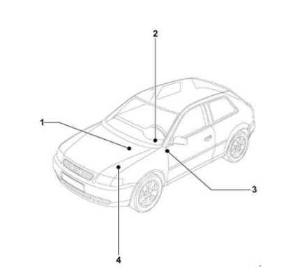

1- Fuse box in the dashboard driver’s side
To access the fuse box located on the left side, open storage compartment behind a cover near the steering column.
Audi A3 8V Fuse Box Diagram – dashboard driver’s side (3)
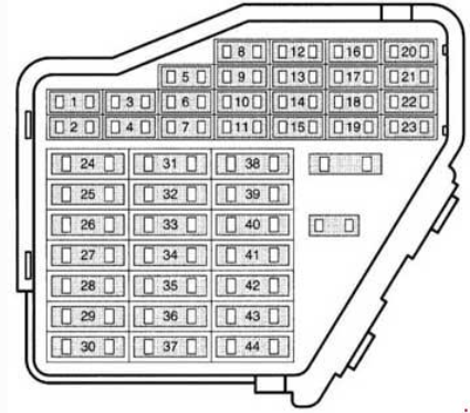
Description

| № | A | Function/component |
| 1 | 10 | S1 – Fuse in relay plate fuse holder Z20 – Left washer jet heater element 75x Z21 – Right washer jet heater element Z4 – Driver side heated exterior mirror Z5 – Front passenger side heated exterior mirror |
| 2 | 10 | M5 – Front left turn signal bulb M7 – Front right turn signal bulb M18 – Left side mounted turn signal bulb M19 – Right side repeater turn signal bulb |
| 3 | 5 | Illuminations: W6 – Glove compartment light E87 – Operating and display unit for Climatronic air conditioning system |
| 4 | 5 | X-number plate light |
| 5 | 7.5 | E87 – Operating and display unit for Climatronic air conditioning system E45 – Cruise control system switch E94 – Heated driver seat regulator E95 – Heated front passenger seat regulator E159 – Fresh air and air recirculation flap switch E221 – Operating unit in steering wheel1) F269 – Temperature flap position switch G65 – High pressure sender J293 – Radiator fan control unit J401 – Navigation system with CD drive control unit J402 – Navigation operating electronics control unit J446 – Parking aid control unit J453 – Multifunction steering wheel control unit R – Radio Y7 – Automatic anti-dazzle interior mirror |
| 6 | 5 | E150 – Driver side interior locking switch V94 – Central locking motor with control unit for interior lights switch-off delay and anti-theft alarm system |
| 7 | 10 | F189 – Tiptronic switch G22 – Speedometer sender G266 – Oil level and oil temperature sender J226 – Starter inhibitor and reversing light relay M16 – Left reversing light bulb M17 – Right reversing light bulb |
| 8 | 5 | J526 – Telephone and telematics control unit J412 – Mobile telephone operating electronics control unit R36 – Telephone transmitter and receiver unit |
| 9 | 5 | E132 – Traction control system switch G85 – Steering angle sender J104 – ABS control unit |
| 10 | 15 | Engine management petrol engine: J220 – Motronic control unit2) J271 – Motronic current supply relay2) J363 – Current supply relay for Simos control unit2) |
| 10 | 5 | Engine management diesel engine: J248 – Diesel direct injection system control unit2) |
| 10 | 10 | J285 – Control unit in dash panel insert3) J402 – Navigation operating electronics control unit3) R – Radio3) V94 – Central locking motor with control unit for interior lights switch-off delay and anti-theft alarm system3) |
| 11 | 5 | G266 – Oil level and oil temperature sender J17 – Fuel pump relay J285 – Control unit in dash panel insert K2 – Alternator warning lamp K14 – Handbrake warning lamp K29 – Glow period warning lamp K132 – Electronic power control fault lamp K149 – Engine electronics warning lamp N110 – Selector lever lock solenoid V48 – Left headlight range control motor V49 – Right headlight range control motor |
| 12 | 7.5 | J401 – Navigation system with CD drive control unit J412 – Mobile telephone operating electronics control unit J526 – Telephone and telematics control unit R36 – Telephone transmitter and receiver unit R86 – Aerial amplifier for mobile telephone T16 – 16-pin connector, black, shelf centre console (diagnostic connector) |
| 13 | 10 | M9 – Left brake light bulb M10 – Right brake light bulb M25 – High-level brake light bulb |
| 14 | 10 | J452 – Door warning lamps control unit V94 – Central locking motor with control unit for interior lights switch-off delay and anti-theft alarm system W – Front interior light W14 – Front passenger side illuminated vanity mirror W20 – Driver side illuminated vanity mirror |
| 15 | 5 | E87 – Operating and display unit for Climatronic air conditioning system G85 – Steering angle sender J217 – Automatic gearbox control unit J285 – Control unit in dash panel insert |
| 16 | 10 | J293-Radiator fan control unit |
| 17 | 7.5 | Z22 – Left lock cylinder heater element Z23 – Right lock cylinder heater element |
| 18 | 10 | L2 – Right headlight twin filament bulb (main beam) K1 – Main beam warning lamp |
| 19 | 10 | L1 – Left headlight twin filament bulb (main beam) |
| 20 | 15 | E102 – Headlight range control regulator J124 – Rear bulb monitoring device J344 – Right gas discharge light control unit L2 – Right headlight twin filament bulb (dipped beam) V48 – Left headlight range control motor V49 – Right headlight range control motor |
| 21 | 15 | J124 – Rear bulb monitoring device J343 – Left gas discharge light control unit L1 – Left headlight twin filament bulb (dipped beam) |
| 22 | 5 | J285 – Control unit in dash panel insert M2 – Right tail light bulb M3 – Right side light bulb |
| 23 | 5 | J285 – Control unit in dash panel insert M1 – Left side light bulb M4 – Left tail light bulb |
| 24 | 20 | J31 – Automatic intermittent wash and wipe relay |
| 25 | 25 | E87 – Operating and display unit for air conditioning system/Climatronic V2 – Fresh air blower |
| 26 | 25 | Z1 -Heated rear window |
| 27 | 15 | J30-Rear window wiper and washer relay V12 -Rear window wiper motor |
| 28 | 15 204) | J17-Fuel pump relay |
| 29 | 15 | Engine management petrol engine: J220 – Motronic control unit J271 – Motronic current supply relay J361 – Simos control unit J363 – Current supply relay for Simos control unit N122 – Output stage |
| 29 | 5 | Engine management diesel engine: J248 – Diesel direct injection system control unit 5) |
| 29 | 10 | Engine management diesel engine: J248 – Diesel direct injection system control unit 6) |
| 30 | 20 | J245-Sliding sunroof adjustment control unit |
| 31 | 20 | J217 – Automatic gearbox control unit J539 – Brake servo control unit |
| 31 | 5 | J492-Four-wheel drive control unit |
| 32 | 10 | Engine management petrol engine: N30-Injector, cylinder 1 N31-Injector, cylinder 2 N32-Injector, cylinder 3 N33-Injector, cylinder 4 |
| 32 | 30 | Engine management diesel engine: J248-Diesel direct injection system control unit |
| 33 | 20 | J31 – Automatic intermittent wash and wipe relay |
| 34 | 10 | Engine management petrol engine: N75 – Charge pressure control solenoid valve N79 – Heater element for crankcase breather N112 – Secondary air inlet valve N156 – Variable intake manifold change-over valve N249 – Turbocharger air recirculation valve N205 – Inlet camshaft control valve 1 |
| 34 | 10 | Engine management diesel engine: G70 – Air mass meter G80 – Needle lift sender N18 – Exhaust gas recirculation valve N75 – Charge pressure control solenoid valve N239 – Variable intake manifold flap change-over valve |
| 35 | 30 | U10 -Trailer socket |
| 36 | 15 | L46 – Rear left fog light bulb L22 – Left fog light bulb L23 – Right fog light bulb |
| 37 | 10 | J285 – Control unit in dash panel insert2) J402 – Navigation operating electronics control unit2) R – Radio2) V94 – Central locking motor with control unit for interior lights switch-off delay and anti-theft alarm system²) |
| 37 | 20 | Engine management petrol engine: J220 – Motronic control unit3) J271 – Motronic current supply relay3) J363 – Current supply relay for Simos control unit3) |
| 37 | 5 | Engine management diesel engine: J248 – Diesel direct injection system control unit3) |
| 38 | 10 | E150 – Driver side interior locking switch F248 – Release button for rear lid lock cylinder J347 – Ultrasonic sensor control unit V94 – Central locking motor with control unit for interior lights switch-off delay and anti-theft alarm system |
| 39 | 15 | Hazard warning lights system : M5 – Front left turn signal bulb M7 – Front right turn signal bulb M6 – Rear left turn signal bulb M8 – Rear right turn signal bulb M18 – Left side mounted turn signal bulb M19 – Right side mounted turn signal bulb K65 – Left turn signal warning lamp K94 – Right turn signal warning lamp |
| 40 | 20 | H2 -Treble tone horn H7 -Bass tone horn |
| 41 | 15 | U1-Cigarette lighter |
| 42 | 15 | J415 – Navigation system tuner for TV J515 – Aerial selection control unit R – Radio R12 – Amplifier R44 – Amplifier with bass loudspeaker, on left in luggage compartment R94 – Navigation system interface |
| 43 | 10 | Engine management petrol engine: G70 – Air mass meter N80 – Active charcoal filter system solenoid valve 1 Z19 – Lambda probe heater Z29 – Lambda probe 1 heater after catalytic converter |
| 43 | 10 | Engine management diesel engine: F36 – Clutch pedal switch F47 – Brake pedal switch N79 – Heater element for crankcase breather J359 – Low heat output relay J360 – High heat output relay |
| 44 | 15 | Z6 – Heated cushion for driver seat Z7 – Heated backrest for driver seat |
2- Fuse box in the engine compartment (4)
To access the fuse box located in the engine compartment, release the fuse cover near the battery.
Audi A3 8V Fuse Box Diagram – Engine Compartment
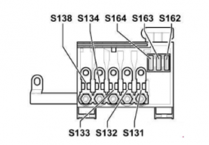
Description

| № | A | Function/component |
| S131 | 50 | Heater glow plugs (diesel engine) |
| S132 | 50 | Engine management |
| S133 | 30 | Radiator fan |
| S134 | 110 | Interior |
| S138 | 150 | Alternator |
| S162 | 30 | Fuse 1 (30) in fuse holder on battery |
The instructions in this tutorial will work in the following model years:
1996, 1997, 1998, 1999, 2000, 2001, 2002 and 2003 – Audi A3 Petrol (1.6 and 1.8) and Diesel (1.9 TDI 90, 100, 110 and 130) Engines, S3.