Audi A6 C6 (2004 – 2011) – Fuse Box Location and Fuses List
December 9, 2018 in Audi A6, Audi A6 C6 (2004 to 2011) by admin
 The Audi A6 C6, Audi A6 C6 allroad, Audi A6 C6 Avant and Audi A6L C6 (2004 – 2011) have 3 fuse boxes location. Two on dashboard passenger and driver side and one in the luggage compartment – Scroll down to see how to access them and the fuses list.
1- Fuse box in the Dashboard driver’s side
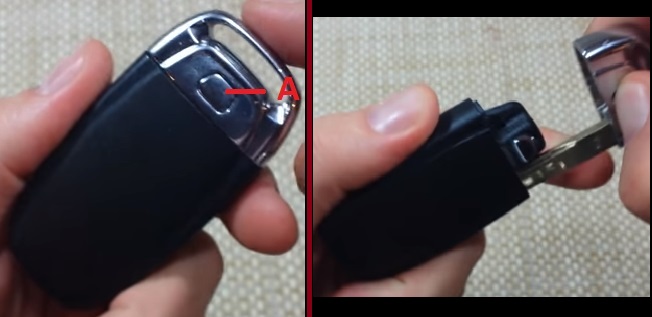
To access the fuse box located on the driver’s side of the dashboard, open the driver’s door and remove the plastic clip (A) from its retainer in the face cover.
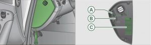
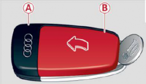
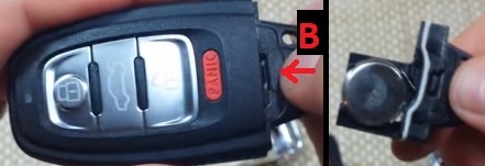
There is a plastic clip (A) in the cover on the left side of the instrument panel, which can be used to remove the fuses. The crank (B) is used for emergency operation of the power roof. You will also find a label on both covers in the instrument panel with the fuse layout (C) for the corresponding fuse panel.
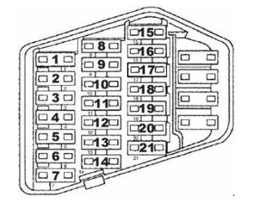
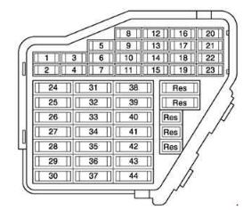
Audi A6 C6 – Fuse Box Diagram – Dashboard driver’s side

Description
| Number | Electric equipment | Amp |
| 1 | Not used | – |
| 2 | Not used | – |
| 3 | Engine management | 5 |
| 4 | Oil level sensor | 5 |
| 5 | Climate control, tire pressure monitoring system | 5 |
| 6 | Electronic Stabilization Program (ESP), clutch sensor |
5 |
| 7 | Diagnostic connector | 5 |
| 8 | Homelink control unit | 5 |
| 9 | Automatic dimming interior mirror | 5 |
| 10 | Adaptive Cruise Control | 5 |
| 11 | Not used | – |
| 12 | Diagnostic connector | 10 |
| 13 | Switch module steering column | 10 |
| 14 | Not used | – |
| 15 | Instrument cluster, control module Gateway | 10 |
| 16 | Telephone, cell phone | 5 |
| 17 | Electronic Stabilization Program (ESP) | 10 |
| 18 | Headlight electronics, left-side | 5 |
| 19 | Rain sensor | 5 |
| 20 | Heated washer nozzles | 5 |
| 21 | Seat adjustment (driver) | 10 |
| 22 | MMI display | 5 |
| 23 | Electromechanical parking brakey | 5 |
| 24 | Not used | – |
| 25 | Not used | – |
| 26 | Not used | – |
| 27 | Not used | – |
| 28 | Not used | – |
| 29 | Not used | – |
| 30 | Not used | – |
| 31 | Back-up light switch, transmission, engine components | 15 |
| 32 | Intelligent power module driver (footwell light and front headlights, horn, wiper system, electrically adjustable steering wheel) | 30 |
| 33 | Intelligent power module driver (lights left-side) | 25 |
| 34 | Intelligent power module driver (lights right-side) | 25 |
| 35 | Not used | – |
| 36 | Headlight washer system | 30 |
| 37 | Electronic Stabilization Program (ESP) | 25 |
| 38 | Wiper system | 30 |
| 39 | Door control module left-side | 15 |
| 40 | Horn | 25 |
| 41 | Heater fan | 40 |
| 42 | Control module electronic ignition lock/electrically adjustable steering wheel | 30 |
| 43 | Rear windshield wiper (Avant) | 15 |
| 44 | Power window opener (left-side) | 35 |
2- Fuse box in the Dashboard passenger’s side
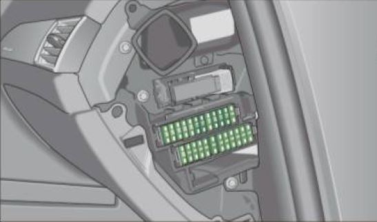
To access the fuse box located on the passenger’s side of the dashboard, you must have the passenger’s door open and remove the side dash cover.
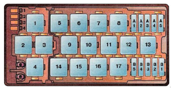
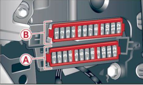
Audi A6 C6 – Fuse Box Diagram – Dashboard passenger’s side
Description
| Number | Electric equipment | Amp |
|
Fuse holder (black) |
||
| 1 | Control module Convenience key | 15 |
| 2 | Cigarette lighter fro nt | 20 |
| 3 | Tire pressure monitoring system | 5 |
| 4 | Electrical outlet front (center console) | 20 |
| 5 | Intelligent power module passenger (glove box lock) |
15 |
| 6 | Door control module righ t -side | 15 |
| 7 | Sunroof | 20 |
| 8 | A/C controls | 10 |
| 9 | Heated seats, front | 30 |
| 10 | MMI | 7,5 |
| 11 | Seat adjustment (passenger) | 10 |
| 12 | Communication | 5 |
|
Fuse holder (brown) |
||
| 1 | Electric fuel pump | 20/30 |
| 2 | Adaptive Air Suspension | 15 |
| 3 | Lane assist | 10 |
| 4 | Audi side assist | 5 |
| 5 | Adaptive Air Suspension | 5 |
| 6 | Shift gate automatic transmission/clutch switch | 5 |
| 7 | Parking System | 5 |
| 8 | Control module Gateway | 5 |
| 9 | Automatic headlight range control (auxiliary driving lights), headlight electronics, right-side | 5 |
| 10 | Airbag | 5 |
| 11 | Heated rear seats | 5 |
| 12 | Telephone | 5 |
3- Fuse box in the Luggage Compartment right
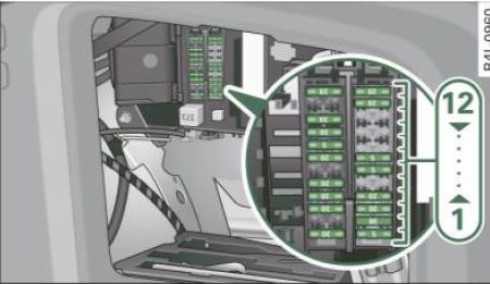
To access the fuse box located on the luggage compartment you should remove the right side trunk trim and open the fuse cover.
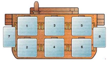
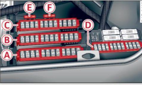
Audi A6 C6 – Fuse Box Diagram – Luggage Compartment right
Description
| Number | Electric equipment | Amp |
|
Fuse holder (black) |
||
| 1 | Digital Signal Processing (DSP)/ BOSE amplifier | 30 |
| 2 | Communication, Antenna amplifier | 5 |
| 3 | Electromechanical parking brake, left | 30 |
| 4 | Electromechanical parking brake, right | 30 |
| 5 | Luggage compartment power outlet | 20 |
| 6 | Battery energy management | 5 |
| 7 | Intelligent power module rear (lights right-side) | 20 |
| 8 | Intelligent power module (comfort) | 5 |
| 9 | Intelligent power module rear (lights left-side) | 30 |
| 10 | Power window opener (right-side) | 35 |
| 11 | Parking System | 5 |
| 12 | Ciga rett e lig ht e r rear | 20 |
|
Fuse holder (brown) |
||
| 1 | Rear view | 5 |
| 2 | Electr ic rear lid (Avant) | 30 |
| 3 | Electric rear lid (Avant) | 30 |
| 4 | Electric rear lid (Avant) | 20 |
| 5 | Communi cat ion, Ant enna a mplifie r | 5 |
| 6 | Not used | – |
| 7 | MMI | 5 |
| 8 | Not used | – |
| 9 | Digital Tuner | 5 |
| 10 | Not used | – |
| 11 | Not used | – |
| 12 | Not used | – |
The instructions in this tutorial will work in the following model years:
2004, 2005, 2006, 2007, 2008, 2009, 2010 and 2011 – Audi A6 C6 Petrol (2.0 TFSI, 2.4 Quattro, 2.4 V6, 2.8 FSI, 3.3 Quattro, 3.2 V6, 4.2 V8, 4.2 V8 Quattro and S6) and Diesel (2.0 and 2.7 TDI, 2.7 V6 and 3.0 V6) Engines.
 The Audi A6 C7 (2011 – 2018) have 3 fuse boxes location. Two on dashboard passenger and driver side and one in the luggage compartment – Scroll down to see how to access them and the fuses list.
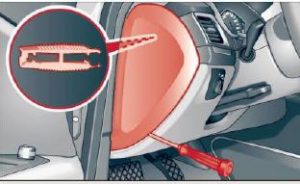

 The Audi A6 C5 (1997 – 2005) have one fuse box of the dashboard driver side – Scroll down to see how to access them and the fuses list.


 The Audi A6 C4 (1994 – 1997) have 1 fuse box and 4 relay box. The fuse box is located in the dashboard driver’s side and the relay boxes in dashboard – Scroll down to see how to access them and each the fuses list.